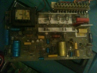
The Bridgeport has a 6F powerfeed and Eskine control boards, there is no circuit diagram on the web.
The initial indication showed the thermal switch had failed so this was bypassed with 5A fuse wire as you will see in the video perhaps not the best idea :-)
Initial investigation of the problem was done see this video:
As you can see the power resistor went bang!
After lots of looking the common issue tends to be with the capacitors, I spent a lot of time trying to test the capacitors in circuit, this was a dead loss, although it may infer an issue it was never conclusive.
I then decided to remove the capacitors and test them out of circuit, long story short due to the age of the capacitors and circuit board I caused more issues than there was originally. No capacitors were faulty, I
crushed capacitors and de laminating traces from the board.
 This photo shows a capacitor which I damaged whilst removing it and the new replacement solder in place.
So after this misadventure I decided to try and reverse engineer the board to understand where the problem may be.
I used LT Spice IV to document the circuit (I didn't finish the circuit, but this is the 80%)
These are the boards that are in the bridgeport mill.
This is the changeover board for the X and Y feed. I was initially confused by the cable colours as some colours were used for different functions.
The review of the circuit showed the issue was with the 110VDC power side so I decided to check the main rectification circuit diodes and thyristors.


Know this is an old post, got a similar problem to yours. Do you got a high res version of that unfinished circuit diagram? Possible to send it to my mail (hanatsu@live.se)? ;)
ReplyDeleteThanks in advance.